Magazine for the professional tire industry
Issue link: https://mtd.epubxp.com/i/762675
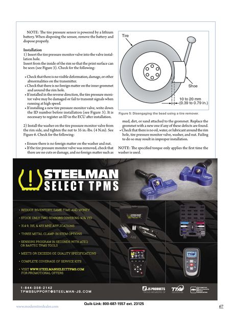
67 www.moderntiredealer.com NOTE: e tire pressure sensor is powered by a lithium baery. When disposing the sensor, remove the baery and dispose properly. Installation 1) Insert the tire pressure monitor valve into the valve instal- lation hole. Insert from the inside of the rim so that the print surface can be seen (see Figure 3). Check for the following: • Check that there is no visible deformation, damage, or other abnormalities on the transmier. • Check that there is no foreign maer on the inner grommet and around the rim hole. • If installed in the reverse direction, the tire pressure moni- tor valve may be damaged or fail to transmit signals when running at high speed. • If installing a new tire pressure monitor valve, write down the ID number before installation (see Figure 3). It is necessary to register an ID in the ECU aer installation. 2) Install the washer on the tire pressure monitor valve from the rim side, and tighten the nut to 35 in.-lbs. (4 N.m). See Figure 6. Check for the following: • Ensure there is no foreign maer on the washer and nut. • If the tire pressure monitor valve was removed, check that there are no cuts or damage, and no foreign maer such as mud, dirt, or sand aached to the grommet. Replace the grommet with a new one if any of these defects are found. • Check that there is no oil, water, or lubricant around the rim hole, tire pressure monitor valve, washer, and nut. Failing to do so may result in improper installation. NOTE: e specified torque only applies the first time the washer is used. Figure 5: Disengaging the bead using a tire remover. Quik-Link: 800-687-1557 ext. 23125